RC Conversion - SB/5 Western Star.
PART 4 - The Rudder And Linkages.
This part is more intricate to carry out.
The original Star yacht setup up was a one-piece tiller arm / rudder set up which enabled the semi-automatic steering. I am going to split the rudder shaft into two sections and by using two servos, will be able to use one for the rudder and the other for the tiller which will act as a sail winch arm.
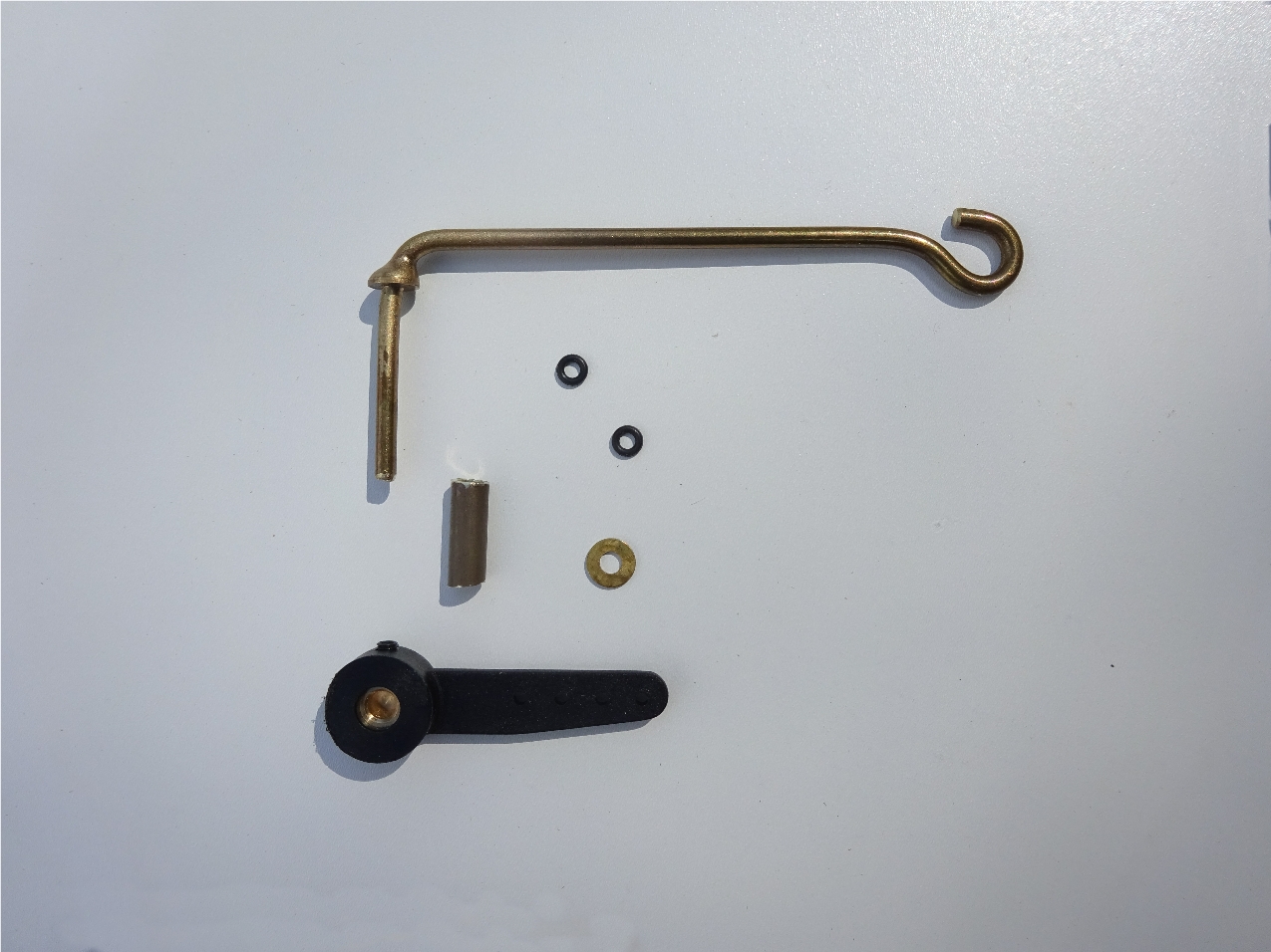
Starting with the tiller arm, as the original was broken, a new one was made from 2.5mm brass rod making the length of it about 13mm longer than original to aid with a bit more throw for sail adjustment. A brass washer was soldered to the neck of the rod just below the bend to act as a weather proof seal. A 17mm piece of the original rudder tube was cut, this will pass through the deck. The original shape of the tiller arm had a flat section with adjustment holes in it, this is not needed on this conversion.
Below, the parts of the tiller arm assembly;
Re-made brass tiller arm, 2 brass washers (1 soldered) 2 nitride seals, a 17mm piece of rudder tube and a 3mm dia. tiller arm (Black).
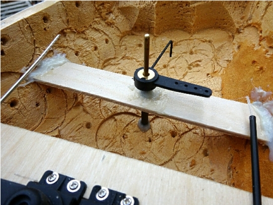
Using the original deck for reference, a hole for the brass tube was drilled through the new deck about 13mm forward of the original position to accommodate the longer tiller arm so that it does not catch on the rear sheet-horse. The brass tube was then fixed into place by using Araldite resin glue and putting enough above the deck to make a capstan shape to stop it falling through the deck, making sure it was vertical. Position the tube to protude below the deck re-inforcing panel by 2mm. The deck was then left until the next day for the glue to cure.
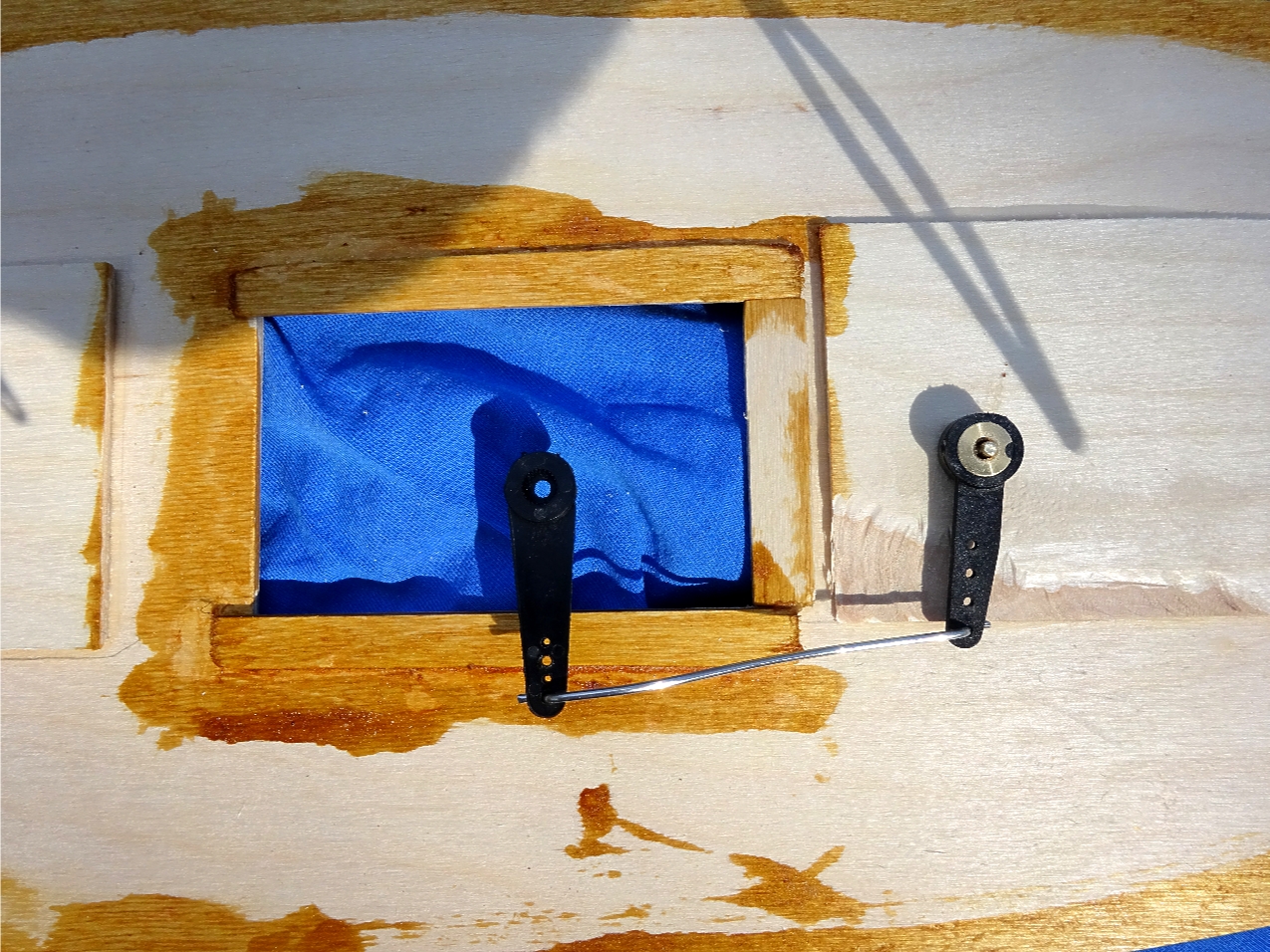
Dry fit the parts together by fitting a seal to the tiller arm to sit under the soldered washer, pass the tiller arm through the brass tube in the deck, fit another seal then a brass washer then the tiller arm (Black) at 90 degrees to the centreline pointing to the right (Starboard) side, make sure they are a good fit together and mark the protruding brass rod. Take note of where the clamping screw fits. Remove all the parts, add an extra 1mm to the length of the brass rod and cut to length, filing the cut edge smooth and adding a flat to where the clamping screw fitted. Re-assemble the parts adding a small amount of grease to below the top seal, lower through the brass tube, adding the remaining items and clamping up the tiller arm.

On to the rudder.
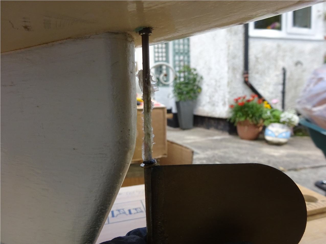
First of all a measurement is needed of the depth of the tiller arm assembly, measuring from below the deck, include the 3mm strengthening plate thickness, take note of the measurement add 5mm for working clearance. Place the remaining rudder tube into the rudder tube hole in the hull so that the bottom of the tube is protruding out underneath about 1mm, place a straight edge across the hull edges and measure down by the measurement taken and mark the rudder tube. Remove the tube and allowing a further 6mm for the rudder tiller arm thickness, cut to length. The rudder parts can now be dry fitted, slide a brass washer onto the rudder shaft followed by a seal, then the rudder tube followed by the other seal, a brass washer and finally the tiller arm pointing to the left (Port) side. Mark the brass rod adding a extra 1mm, disassemble and cut the rod to length filing a flat for the clamp screw. The tube can then be placed into position and the rudder parts re-assembled, placing the deck onto the hull to check for a working clearance, once happy, disassemble the parts and a brace plate can be fabricated to hold the tube in a vertical position. When happy with the position, bond the tube and brace into place and leave to cure.
After setting, assemble the rudder adding a fair amount of grease to the bottom of the shaft as it is pushed into the tube, add the seal, brass washer and tiller arm, push together for a good fit and clamp up the arm to the flat on the shaft.
It's important to add grease to the bottom of the rudder shaft to act as a further water-proofing.
For the linkages, I am using 1.5mm stainless wire, this is my preferred choice as it is simple to fabricate, this process will require a lot of "Fettling", there are other methods of doing this, using alternative rods / slider clamps will make the job easier but may require more clearance around the parts.
Starting with the rudder, position a servo arm on the left hand servo and note the distance to the rudder tiller arm, cut a couple of lengths of stainless wire allowing an extra 25mm, using pliers, bend a double 90 degree dogleg into one end of the stainless wire and at the noted length bend another dogleg, it may be a case of practice makes perfect but you will get a satisfactory fit then trim any excess length off the wire. The provided adjustment holes in the nylon arms may need widening slightly to take the wire, you can do this with a small drill bit to get a snug fit. Once happy, fit to the rudder arm first, then remove the servo arm, fit the wire and refit the servo arm. Any slight adjustments to the rudder position can be taken up on the transmitter trim adjustment. Make another wire of the same dimensions and try into position for the tiller arm, to test fit the deck in place and connect together, if the position is way out then make another wire allowing for the length adjustment. When happy with all of the fit, the servo screw for the rudder can be fitted, the tiller servo screw is fitted after the deck is in place. You can at this point apply a small amount of grease to the arms / wire joint for lubrication.