RC Conversion - SB/5 Western Star.
PART 2 - The Hull Preparation.
The first thing that I do is give the inside of the hull a couple of coats of yacht varnish spray to waterproof the inside of the hull. Then using a wood filler, I filled in the pin holes left from the side rubbing strips and all the deck pin holes around the deck edge. I decided to remove the central deck brace as it would be in the way of access to components through the hatchway, I will be replacing it later on in a slightly different position, the mounting holes for this were also filled.
Making The Carrier Panel.
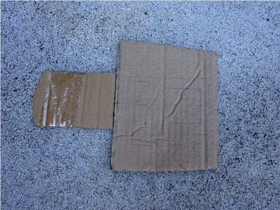
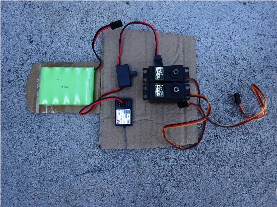
Starting with laying out the main components, the two servos, one for the rudder and the other for the sail winch arm, the receiver, the on / off switch and the battery. I weighed all the components and the battery was almost exactly the same weight as all the other parts together, using the mark on the hull side it was easy to split the parts 50 / 50 for balance. Cut out a card template to fit the inner shape of the hull leaving enough space below the hull edge to clear the servo tops, when happy transfer the shape to a piece of plywood leaving a little excess on the width for adjustment. On this yacht there will be a hatchway of 100mm x 70mm for access, bearing this in mind, keeping everything central, mark out where the servos are going to be placed and cut out either by chain link drilling or by a mini-drill cutting wheel, file all cut edges smooth. I find it helps to sink the receiver into a cut hole as well. For the battery, I cut a small piece of plywood to be glued into place on an angle so that in the future the battery can be pulled out through the hatchway if need be.
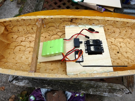
The plywood parts are trimmed to fit then epoxy glued into the hull checking for position and height clearance, leaving to cure.
The two servos are positioned centrally and screwed into place with the splines for the servo arms to the rear. The receiver is glued into place along with the on / off switch positioned in a way that the toggle faces inwards for easy operation. Once dry the receiver aerial wire can be pushed through the tube provided in the kit and the tube glued down to the plywood. A piece of velcroe is glued to the sloping piece of ply and the battery so that they can be attached together. The original deck brace was re-profiled and bonded into place ahead of it's original position, the carrier panel will also add rigidity to the hull.
After charging the batteries, it is worth a trial fit of the electrical connectors and set up the transmitter to check that both the servos are working okay.