RC Conversion - MK/4 Endeavour.
PART 4 - The Deck & Hatch.
I was lucky in that the deck was removed in good order and one piece, this does not always happen. I will add a separate procedure for making a new replacement later but for this part I will be using the existing deck.
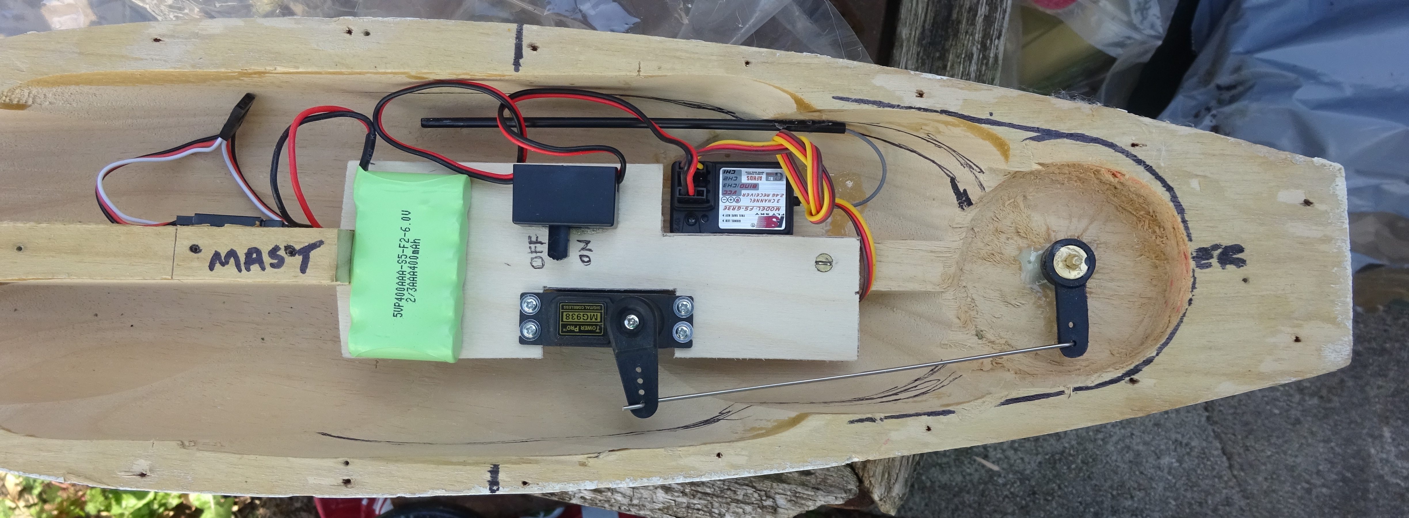
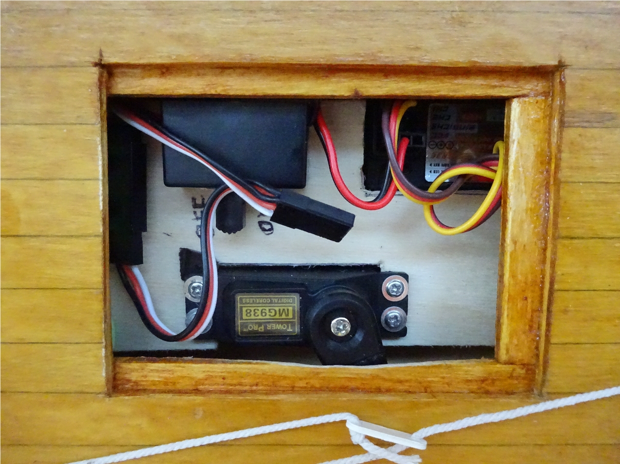
Below is the layout for the components, you will need enough access to be able to turn the power on, or to replace the servo or battery if necessary. To keep the appearance of the hatch low profile, I will be using the original plank lines to hide the side cuts. The size of the hatch will be approx 60 x 75mm.
Prepare the deck by removing any fixing pins that may still be there and if there was a steering quadrant fitted, snip the 2 quadrant pins back to the plywood so that they do not interfere with moving parts in the hull.
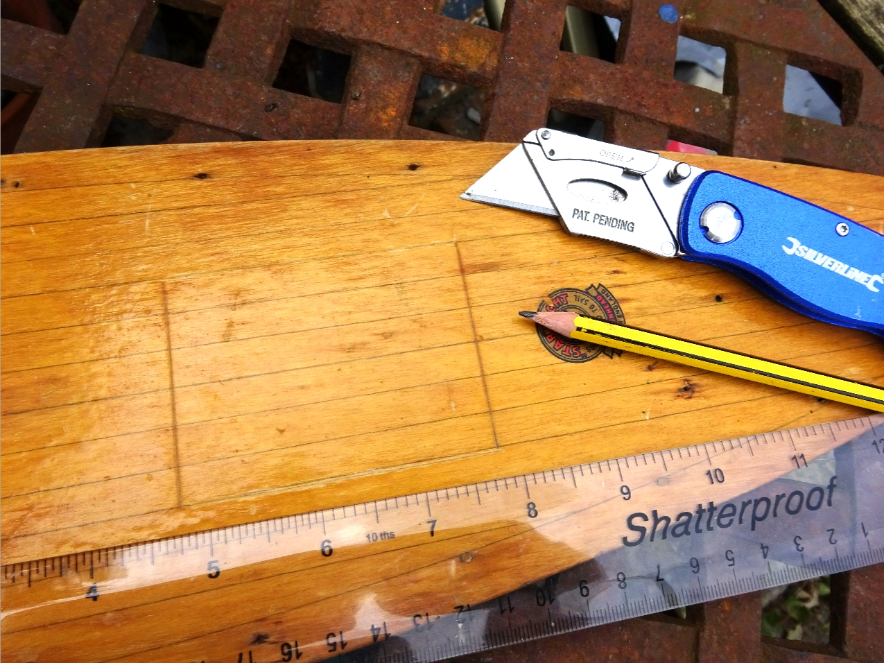
Position the deck over the hull and make a pencil mark midway between where the rear of the battery and the on/off switch are, transfer this mark to the central plank line and then make another mark 75mm rearwards. From these two marks go out 3 plank lines either side and this is width needed, join up all the marks to make an oblong shape, check for squareness. See photo below.
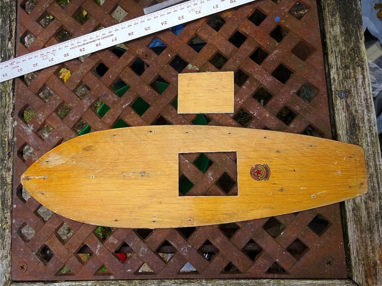
Next find somewhere solid to lay the deck flat on (Not the dining room table!) and using a metal rule with a heavy duty craft knife (Stanley knife) start to score along the marked lines, keep doing this for some time until you have gone through most of the thickness of the ply, then using the point of the blade, at the corners gently piece through the plywood so that you can see the corners from the underside. Use a pencil and join up the corners then continue to score the lines with the knife, eventually you will break through the ply and carefully remove the hatch portion. All edges can then be smoothed with a fine file if necessary, make a pencil mark underneath so that you know which way the hatch will fit on re-assembly. Place the deck over the hull to test access.
The Hatch Frame And Clip.
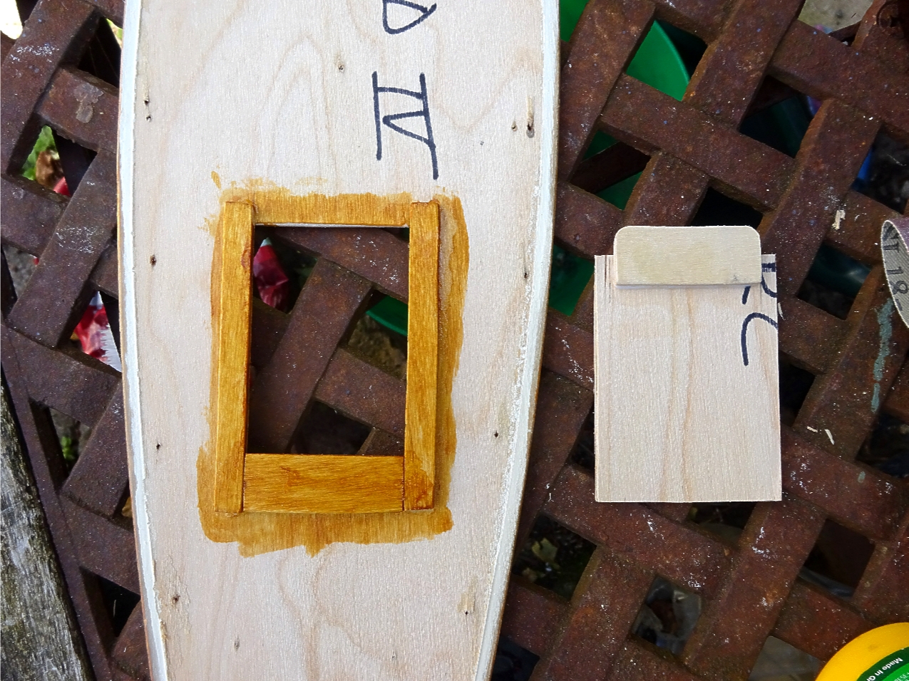
Cut 2 pieces of ply about 8mm wide and 20mm longer than the hatch opening and another 10mm wide by 52mm long, these are for the hatch frame that the hatch will sit on. Using PVA glue, attach the side lengths midway over the hatch opening, with an equal overlap front and rear, at the same time position the rear piece with an overlap to match the side members. Leave to dry.
Cut another piece of ply, this time about 45mm x25mm, this is attached to the front of the hatch so that it can slide under the deck to lock it in place when closed. Apply some glue and fix in place centrally with a 50 / 50 overhang. See photo below.
.JPG)
When dry, use a coat of shellac to seal all the bare wood.
Next is to make the hatch seal down and for this I have used a spring clip mechanism but you may have your own methods such as magnets or swing lock.
Here are the parts needed for the spring lock mechanism. A screw eye, a washer, a stainless wire clip and a ply pad.
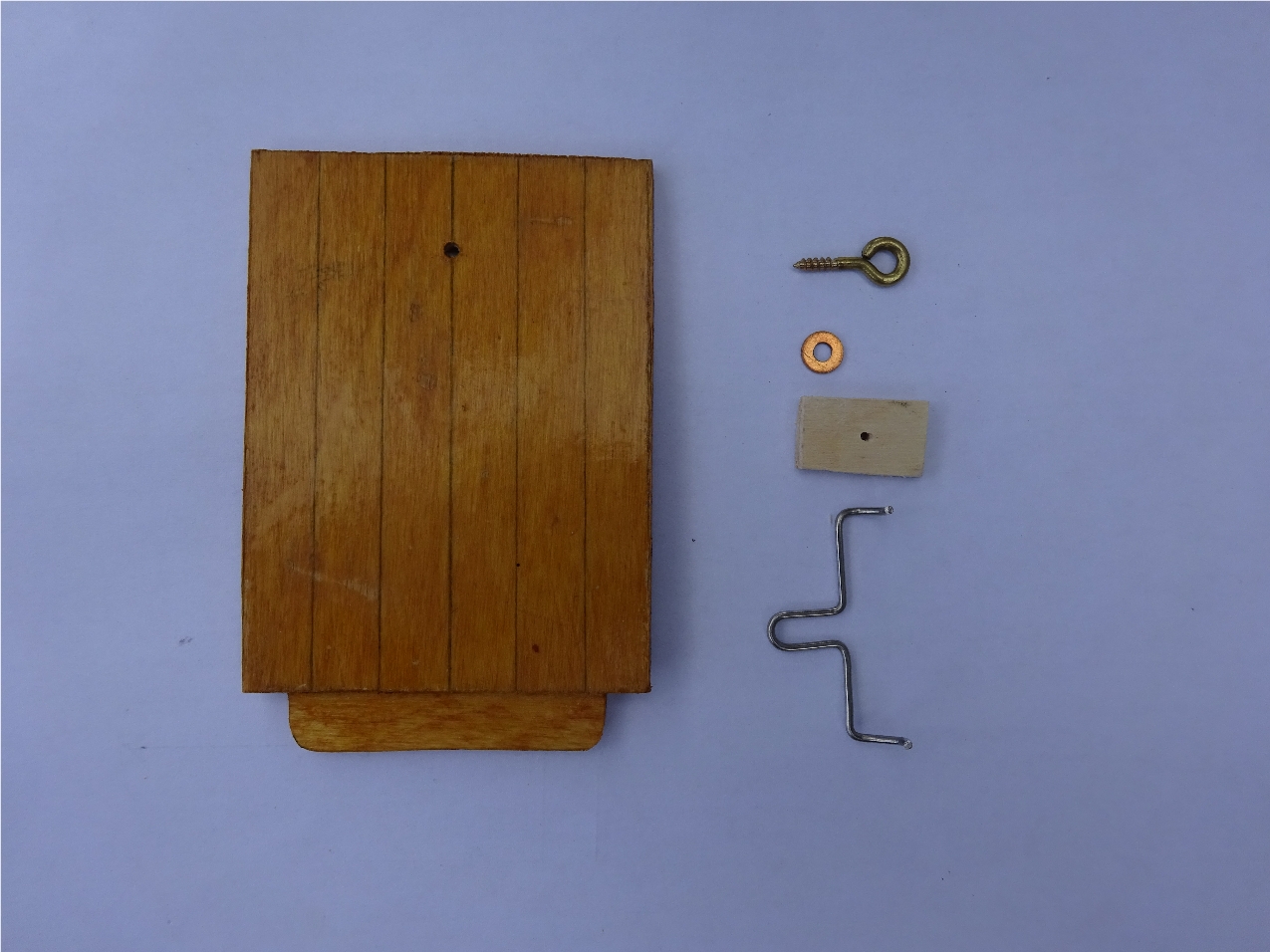
I drilled a 1mm hole, 13mm from the rear edge on the central plank line. The off cut of ply is approx 10mm x 20mm.
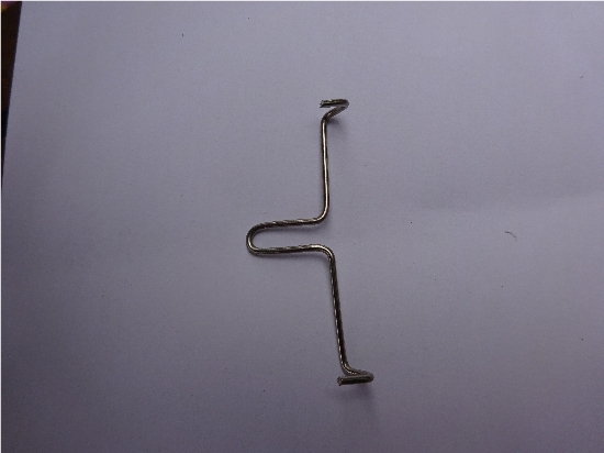
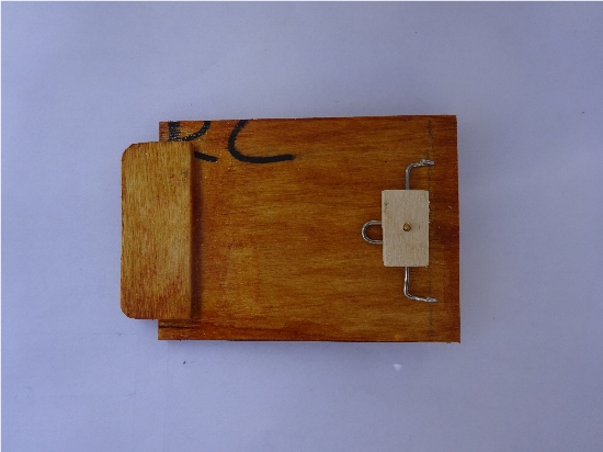
Now the fiddly bit, making the spring clip from 1.5mm stainless wire but you can substitute for another type. The screw eye goes through the washer, then the clip and finally screws into the pad. By adjusting the clip forwards and backwards, then tightening everything up, you should be able to get a good tight fix on the hatch. No rubber seal is needed on the hatchway as the parts fit very close together, the only thing added was just before sailing, a small amount of vaseline was smeared around the hatch frame to be doubly sure of being watertight.
Final check - once you have completed the hatch, the deck can be replaced onto the hull, loosely place the deck back over the hull and power up the RC to move the linkage back and forth to check if any of the linkage catches on the hatch frame, this can happen and if so, you can remove a small amount of framework underneath that catches with a half round file until the linkage moves freely.
Make sure that you position the battery charging point on the splitter cable within the hatch opening area.
As my deck was in good condition I applied glue around the hull face, I fixed it back into the exact same original position by poking two small lengths of wire through deck holes into the corresponding holes in the hull face, then using slightly oversized brass panel pins, went around the deck and using the original holes in the deck, pinned the deck down. The hull was left to dry.
Once dry, I painted the new rudder and the cleaned up existing steering rack along with a newly made false tiller arm green as per original. The steering rack was pinned into place using a shortened pin on the port side so as not to foul the linkage movement underneath, the tiller arm was glued into the existing hole in the deck and positioned to look original fitment.
-550.JPG)
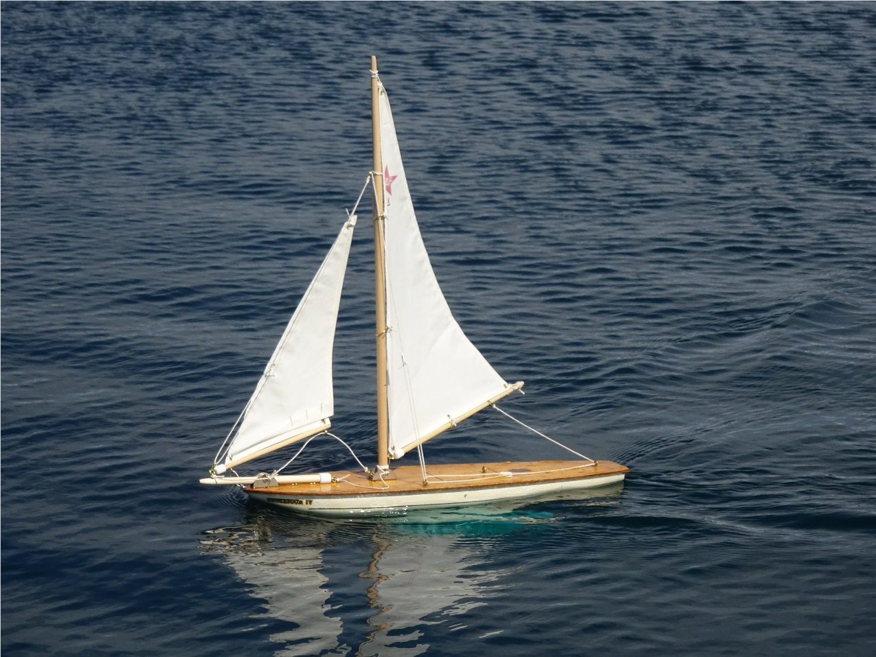
All that was left to do was to replace the deck furniture, mast and spars along with the sails, re-rigging with new cord at the same time.
Sailing setup is easy as you only need to set the position of the sails to match the wind conditions and steer using the transmitter.
Update on fitting a shop bought rudder assembly.