RC Conversion - MK/4 Endeavour.
PART 4 - The Electrics.
Electrics baffle people but don't be put off as this conversion has only 5 parts, a battery, a receiver, a servo, an on/off switch, a splitter cable and all of them are push fit with no soldering needed. Make sure that you use the same connector on all of the items. Here I am using one of the commonly found types, the JR or Futaba fitting.
First of all get all the batteries that you are using and fully charge them.
Here are the individual items needed;
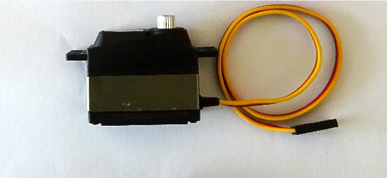
The servo, I am using a Mini servo which is ideal for this conversion due to it's size and weight. Always use a servo with metal gears, this is important as servos with plastic gears tend to strip the gears after not much use. More on servo sizes here.
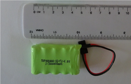
The battery, 400mAh, other sizes are available, 320mAh is an alternative, consider the weight on any larger ones.
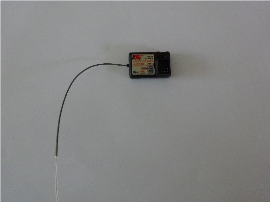
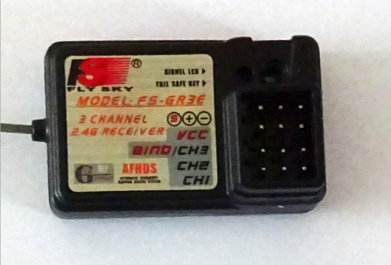
The RC receiver, most types are this shape, this is a 2 channel type that came in a set with the transmitter.
The on/off switch, various types are available.
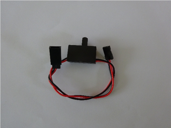
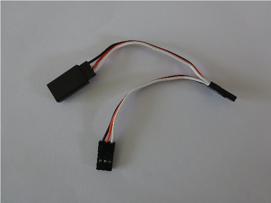
The cable splitter, I fitted one of these to make charging the battery easier instead of having to disconnect the battery every time you just plug the charger onto the spare connector.
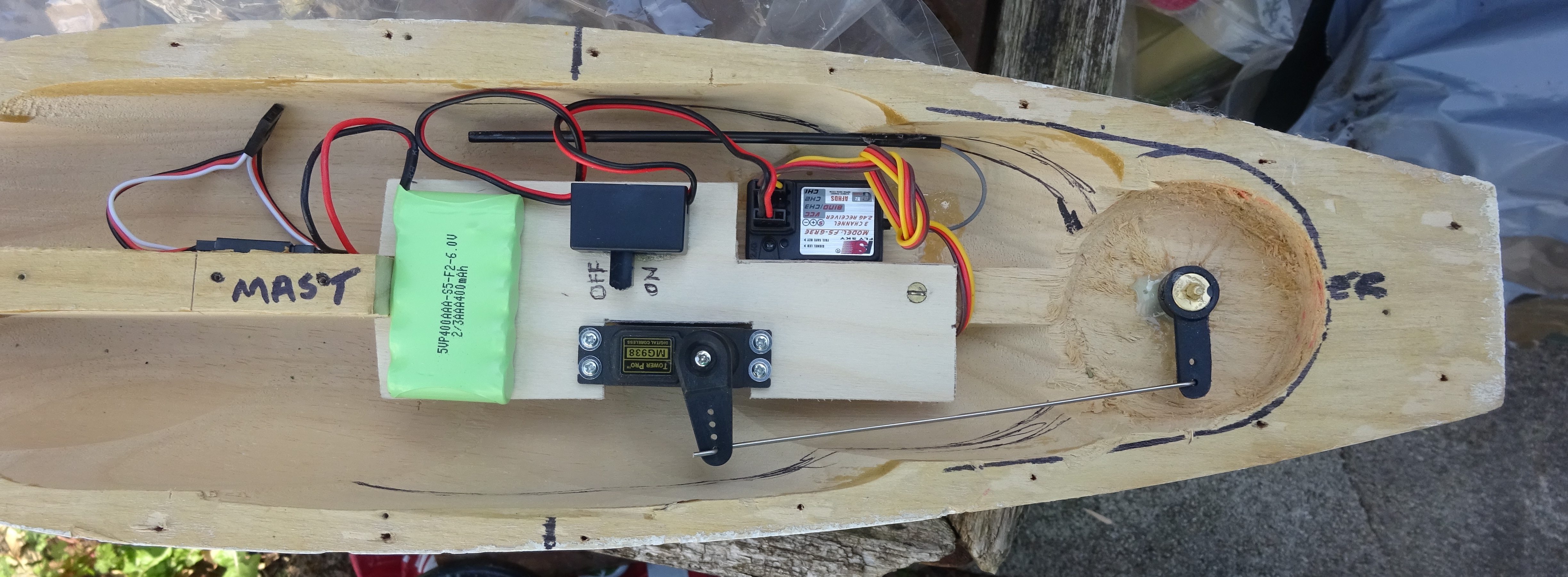
This is how they will look in situ. Click on for larger image.
Parts fitment.
Start by screwing the servo in place, place with the servo arm to the rear. Next using a contact adhesive like clear Bostick, glue the receiver onto the lower plywood plate with the cable connector block towards the bow. Glue the on/off with the toggle facing inwards adjacent to the servo position. The battery is fixed in by velcro so that it is removable, glue a piece about 25mm to the back of the battery and a central position over the front fixing screw. Lastly, if there is one in your transmitter kit, fit the aerial wire into the aerial guide tube and glue the guide tube onto the hull wall adjacent to the receiver, leave all to dry.
Connecting the parts.
Starting with the battery, connect the lead to the female connection on the splitter cable.
Take the on/off switch, check that the switch is in the OFF position, connect the female connector to one of the male connectors on the splitter cable. The spare male connector of the splitter cable is for connecting to a battery charger.
The male connector on the on/off switch connects to the power connection on the receiver, look carefully at photo, it is at the top marked VCC, fit with the black cable on the lead to the right, red to the centre.
Take the lead from the servo and plug it into the bottom, CH1 connection on the receiver, servo cable colours may be different and the black cable can sometimes be brown.
If you have bought a complete RC transmitter kit, then that all that needs to be done.
(If you are putting together your own items, then you will have to perform a "Bind" to link the transmitter to the receiver, refer to your transmitter instructions for this.)
The servo setup will have to be tested before connecting the servo arm to the tiller arm. Always turn on the transmitter first, then turn the on/off switch to the ON position, if all is well then you should hear a short "Whizz" noise as the servo sets itself up to centralise itself, the receiver led should be showing a continuous red. Try to operate the servo with the steering on the transmitter. When happy, turn off. Always turn off the transmitter first, then turn the on/off switch to the OFF position, the led will extinguish.
PART 5 The Servo/Tiller Linkage.